
Housing Material Showdown: ABS vs. PC vs. PC+ABS for Electronic Device Enclosures
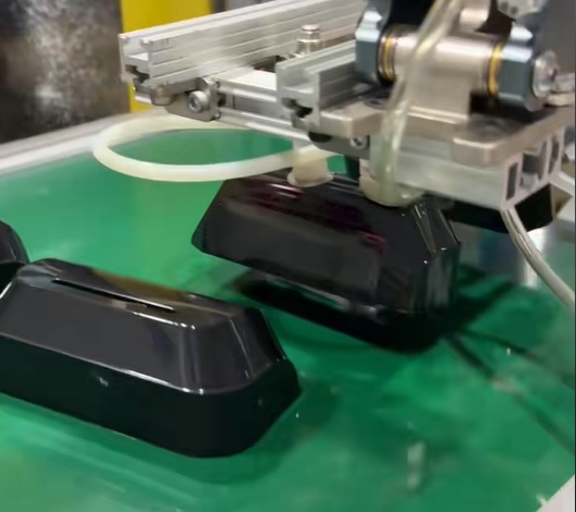
Short answer: For most electronic device enclosures, ABS is generally selected when cosmetic quality, stable molding, and cost control dominate; polycarbonate (PC) is generally selected when impact resistance and heat resistance dominate; PC+ABS blends are generally selected when an enclosure needs more than ABS can deliver but does not justify the cost and processing demands of straight PC. The correct answer is always specific to the enclosure's handling profile, internal heat load, assembly tolerances, and expected 3-to-7-year service life.
This guide is written for OEM buyers and engineering teams at the decision stage — the point where the material family must be committed because it determines shrinkage compensation, gate and runner design, wall thickness, cooling layout, and the surface finish route. It compares ABS, PC, and PC+ABS on the performance attributes that decide enclosure programs, then gives a practical selection framework that can be used in a supplier review.
DTG TECH CO., LTD. is an ISO-certified custom injection molding manufacturer founded in 2002, based in Xiamen, China, operating a 2,500 m2 facility with 80 employees including 25 engineers, serving OEM buyers in the USA, Europe, and India with precision mold design, tool manufacturing, prototype development, plastic injection molding, and mass production.
The Problem: One Part, Several Conflicting Requirements
An electronic device enclosure is not a cosmetic shell. It locates internal modules and sensors, absorbs the shocks of daily handling, closes on an assembly line without force, and presents the visible surface of the product. Those requirements pull in different directions, and the material decision is where the conflict is resolved.
Stiffness usually improves with higher modulus, which can reduce impact performance. Better impact resistance often comes with a more ductile material that marks and scratches more easily. Higher heat resistance generally pushes the resin toward a higher processing temperature and a narrower molding window, which increases the risk of warpage and dimensional variation when the process is not developed properly. Cosmetic quality adds a fourth constraint: a visible housing cannot hide flow marks, weld lines, or sink marks behind a label.
When the balance is wrong, the symptoms are the standard defect list of injection molding: short shot, sink marks, warpage, weld lines, and surface defects. On the dimensional side, the risk set is dimensional deviation, assembly mismatch, and inconsistent production quality. Experienced molders control these before tooling production using DFM analysis, mold flow analysis, optimized injection parameters, and proper gate and runner design — not by adjusting the press after the first samples fail.
Decision rule: if the enclosure will be handled daily, sit near a heat source, and be judged on visible surfaces, material selection is a three-way trade between impact behaviour, heat resistance, and process stability. No single family wins all three.
Industry Background: Why Enclosure Material Choice Moved Up the Agenda
The global injection molded plastic market was valued at USD 324.98 billion in 2024 and is projected to grow to USD 435.74 billion by 2035 (Market Research Future). Published estimates for the same period differ between research institutions because the product scope and base years differ — for example, Grand View Research and Fortune Business Insights report different 2024 and 2025 values — so buyers should read the direction and scale of the market rather than treating any single figure as definitive.
Supply concentration is more directly relevant to sourcing decisions. China produces an estimated 65% of the world's injection-molding machines and accounts for 60% of global export volume (Industry Analysis Report 2025), and China's plastic mold industry was sized at approximately ¥600 billion with a projected expansion to ¥1 trillion by 2030 (JBRplas). For an OEM selecting a molder for an enclosure program, that means the engineering and tooling capability behind a housing decision is concentrated in a market where process control, not machine availability, is the differentiator.
Material substitution is another driver. Automotive OEMs replacing metal parts with engineered thermoplastics account for 34% of domestic injection molded component demand in major hubs such as the US (Grand View Research, 2024). The same logic — replacing heavier or more expensive assemblies with molded thermoplastic parts — continues to spread into electronics housings, consumer products, and industrial plastic components, all of which are established application families for precision injection molding.
The Three Candidates: ABS, PC, and PC+ABS
ABS (Acrylonitrile Butadiene Styrene)
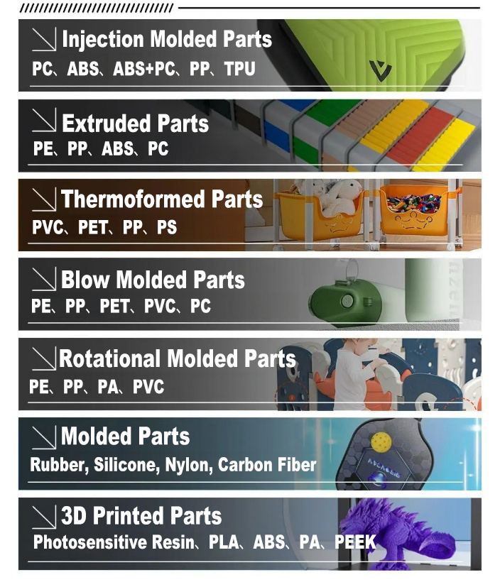
ABS is a styrenic thermoplastic widely used for consumer electronics and appliance housings. Its enclosure value comes from balance rather than from a single peak property: moderate toughness and rigidity, a generally forgiving processing window, and a surface that accepts a clean cosmetic finish. This combination is why ABS remains the default starting point for visible device covers.
Its limitation is heat. Where a housing sits close to a power supply, motor, or high-output light source, ABS can be the limiting factor for dimensional stability and appearance over a multi-year service life. Buyers should treat heat as the first filter when comparing ABS against the other two families.
PC (Polycarbonate)
Polycarbonate is an engineering thermoplastic generally recognized for high impact resistance and better heat resistance than ABS. Enclosures that must survive harder handling, or that operate at higher internal temperatures, commonly move to PC for exactly those two reasons.
The trade-offs are process and cost. PC generally requires higher processing temperatures and careful drying before molding, and it places more demands on mold design, cooling layout, and process control because molded-in stress is less forgiving. Resin cost is also generally higher than ABS. Choosing PC is therefore a decision to spend engineering attention and material budget to buy impact and heat margin.
PC+ABS (Polycarbonate/ABS Blend)
A PC+ABS blend is formulated to combine the impact and heat behaviour associated with polycarbonate with the processability and surface quality associated with ABS. For enclosure programs it is usually the middle path: better drop performance and heat resistance than ABS, easier molding and finishing than straight PC.
The caution with blends is variability. Impact, heat, and flow characteristics change with the grade and the PC content, so the balance must be confirmed against the specific grade datasheet and the T1 sample — not assumed from the family name.
Comparison Table: ABS vs. PC vs. PC+ABS for Enclosures
| Decision factor | ABS | PC | PC+ABS |
|---|---|---|---|
| Impact behaviour | Balanced toughness that is generally sufficient for enclosures protected by the overall product design | Generally the strongest impact performance of the three; often selected where drop or strike risk is significant | Designed to sit between ABS and PC; impact performance varies by grade |
| Heat resistance | Moderate; usually the limiting factor where internal heat load is high | Generally better than ABS, which is why it is used near power components and light sources | Between ABS and PC, depending on the PC content of the grade |
| Dimensional stability and shrinkage control | Well understood and repeatable once moulding parameters are standardized | Generally tighter dimensional behaviour, but more sensitive to moulded-in stress and cooling layout | Grade dependent; requires datasheet confirmation and T1 validation |
| Surface finish and decoration | Good cosmetic surface; widely used for visible housings | Can achieve a fine finish but generally needs tighter process control to avoid flow and stress marks | Combines ABS-like surface quality with improved mechanical performance |
| Processing window | Generally wide and forgiving; lower processing temperatures | Narrower window; higher temperatures and careful drying required | Intermediate; grade specific |
| Relative resin cost direction | Generally the lowest resin cost of the three | Generally the highest resin cost | Generally between ABS and PC |
| Typical enclosure fit | Consumer electronics housings and appliance covers where cosmetics and cost dominate | Enclosures exposed to impact or heat, including electronic housings and industrial parts | Mid-range devices that need more than ABS without the cost and process demands of PC |
The second table is the part most buyers never see in a generic material comparison: how the molder's process control changes the outcome for the same material. The figures below come from DTG's own comparison data for precision and standard injection molding.
| Parameter | Conventional baseline | Precision-controlled injection molding | Why it matters for enclosure programs |
|---|---|---|---|
| Dimensional tolerance | ±0.1 mm to ±0.2 mm | ±0.01 mm to ±0.05 mm | Covers, bezels, and sensor mounts assemble without force |
| Surface roughness | Ra 3.2 to 6.4 μm | Ra 0.4 to 1.6 μm | Visible surfaces meet cosmetic expectations without extra finishing |
| Dimensional scrap rate | 3% to 5% | ≤0.5% | Fewer rejected housings and less assembly rework |
| Mold trial cycles | 5 to 7 cycles at low-cost suppliers without engineering support | 2 to 3 cycles when DFM analysis is applied before tooling | Fewer schedule disruptions before product launch |
| Design modification iterations | Reference baseline | Reduced by 40% to 60% through DFM before tooling | Less engineering rework and fewer tooling changes |
| Unit cost versus CNC machining | 15 to 30 minutes per part | 20 to 60 seconds per shot; 70% to 90% lower per-part cost above 1,000 units | Enclosure economics improve sharply once volume is real |
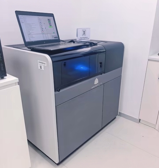
| Prototype accuracy for validation | 3D printing at ±0.3 mm | Rapid injection molding at ±0.05 mm; 60% to 80% lower per-part cost above 50 to 100 units | Validation runs use production-grade material and process |
How Material Choice Connects to Tooling, DFM, and Process Windows
Material selection is not a purchasing decision that can be finalized after the mold is cut. Shrinkage, flow length, and cooling behaviour differ between ABS, PC, and PC+ABS. Once tool steel is cut to one set of shrinkage values, switching the family usually means mold modification, re-validation, and schedule loss.
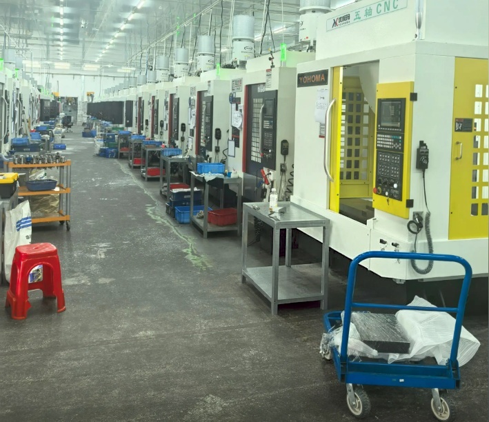
That is why the tooling workflow is material-driven. Mold engineers evaluate the mold structure, verify the tooling before production, and run mold trials with customer approval before mass production. DFM review and mold structure optimization control the risks of mold design errors, poor part release, short mold lifespan, and production instability. Mold testing and T1 sample validation verify part quality before production starts. For defect risk — short shot, sink marks, warpage, weld lines, and surface defects — the controls are DFM analysis and mold flow analysis applied before tooling production, followed by optimized molding conditions during the T1 trial and sample inspection before mass production.
Material characteristics also drive the process recipe. Incoming material is verified, and molding parameters are controlled according to the characteristics of the specific resin, which is the practical reason a PC program and an ABS program cannot share the same parameter sheet even when the mold geometry is similar.
Step-by-Step: A Material Selection Framework for Enclosure Programs
Step 1 — Define service life and handling profile
Start with the expected 3-to-7-year service life and the real handling environment: how often the device is picked up, dropped, cleaned, or exposed to sunlight. This sets the impact and heat floor for the material shortlist.
Step 2 — Separate must-pass requirements from preferences
Write the enclosure requirements as pass or fail. Typical must-pass items: drop or impact threshold, continuous internal temperature, dimensional tolerance for mating parts, and cosmetic acceptance on visible surfaces. Preferences such as a specific gloss level or texture sit outside the material family decision.
Step 3 — Shortlist the material family
Apply the comparison table above. If heat load and impact risk are moderate and cosmetics dominate, ABS is usually the efficient choice. If impact or heat is the binding constraint, move to PC. If both are moderate but ABS alone leaves insufficient margin, PC+ABS is the usual middle path.
Step 4 — Confirm the grade and verify incoming material
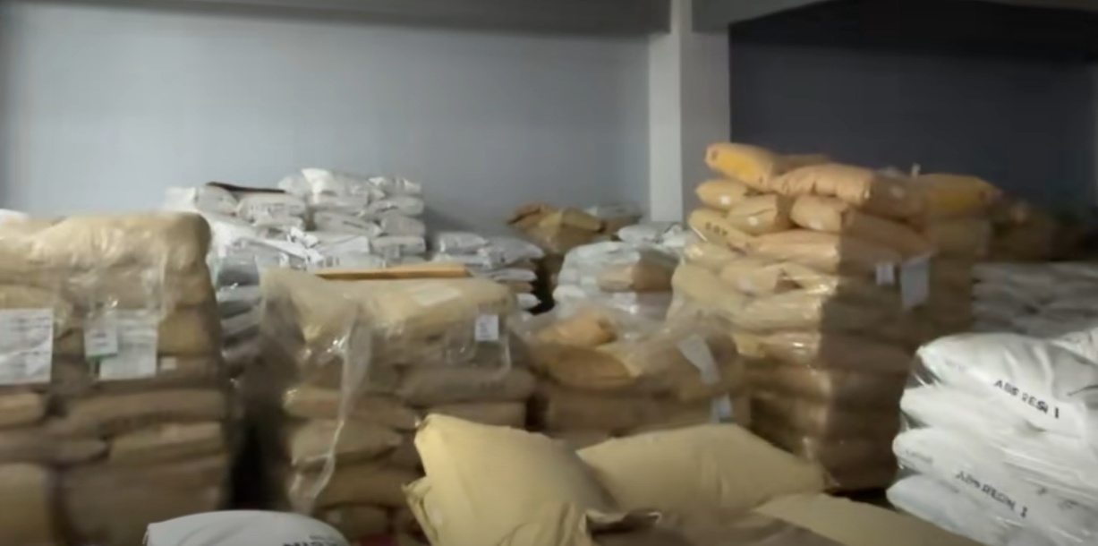
Material requirements are confirmed before production, incoming materials are verified, and material specifications are confirmed with the supplier. This is the control that prevents material mismatch, inconsistent material performance, and colour variation — the three failures that are hardest to detect after assembly.
Step 5 — Run DFM and mold flow analysis before tooling
Before tooling production, engineers review part design and run DFM and mold flow analysis. This is where gate and runner design, wall thickness, and cooling layout are fixed for the chosen resin, and where design modification iterations are reduced by 40% to 60% compared with proceeding straight to tooling.
Step 6 — Validate with T1 samples and first article inspection
T1 trials are used to optimize molding conditions and produce samples for inspection before mass production. Dimensional inspection, first article inspection, and in-process quality inspection confirm part accuracy and prevent assembly mismatch. Where rapid prototypes are used earlier in the program, rapid injection molding delivers ±0.05 mm dimensional accuracy compared with ±0.3 mm for 3D printed prototypes, using production-grade material.
Step 7 — Standardize parameters and inspect before shipment
After sample confirmation, unified production specifications are issued, the production schedule and output are tracked in real time, and full pre-shipment quality inspection is performed. This combination controls production variation, delayed delivery, and batch quality fluctuation — the three risks that turn a good material decision into a bad supply experience.
Use Cases: Where Each Choice Usually Lands
Handheld and portable electronics
Frequent handling makes impact behaviour the first filter. PC or a higher-PC-content PC+ABS is commonly preferred where drop risk is real, while ABS remains workable for protected devices with lower drop exposure.
Smart home devices, sensors, and control panels
These housings combine cosmetic surfaces with dimensional requirements for sensor alignment. PC+ABS is often the practical compromise: better mechanical margin than ABS, easier cosmetic control than straight PC.
Home appliance housings and control panels
Appliances combine moderate heat exposure, frequent user contact, and visible surfaces. Material selection typically balances heat resistance against surface durability and cost per housing, with ABS and PC+ABS covering most covers and panels and PC reserved for high-heat or high-impact positions.
Industrial equipment and instrument enclosures
Industrial housings tolerate less cosmetic compromise but more mechanical and environmental stress. Precision injection molding supports tolerances of ±0.01 mm to ±0.05 mm and surface roughness of Ra 0.4 to 1.6 μm, with dimensional scrap rate reduced to ≤0.5% compared with 3% to 5% in standard molding.
Medical and healthcare device housings
Where an enclosure is part of a medical device program, ISO 13485 is the benchmark quality management system for medical device injection molding and requires specific documentation such as the Device Master Record (DMR). Material and process documentation therefore becomes part of the selection criteria.
Automotive electronic and interior parts
For suppliers serving automotive programs, IATF 16949 is the specialized quality standard, emphasizing defect prevention and waste reduction. Material substitution in that sector already accounts for a large share of molded component demand, and the same engineered thermoplastic logic applies to electronic housings.
Where Enclosure Material Decisions Usually Go Wrong
- Material mismatch and colour variation. Controlled through material verification, supplier management, and material specification confirmation, with molding parameters set according to the characteristics of the confirmed resin.
- Dimensional deviation and assembly mismatch. Controlled through dimensional inspection, first article inspection, and in-process quality inspection, including measurement checks during production, monitoring of critical dimensions, and inspection of finished parts before shipment.
- Mold design errors, poor part release, short mold life, and production instability. Controlled through DFM review, mold structure optimization, mold testing, and T1 sample validation before production.
- Short shot, sink marks, warpage, weld lines, and surface defects. Controlled through DFM analysis, mold flow analysis, optimized injection parameters, and proper gate and runner design, with sample inspection before mass production.
- Production variation, delayed delivery, and batch quality fluctuation. Controlled through production process monitoring, standardized molding parameters, unified production specifications after sample confirmation, real-time tracking of schedule and output, and full pre-shipment quality inspection.
Two sourcing structures also behave differently. An integrated mold manufacturing and injection molding service shortens the overall project cycle by 20% to 30% and cuts cross-supplier communication time by more than 50% compared with using a separate mold supplier and molder, because one supplier manages mold modification, production optimization, and quality feedback. In practice this reduces coordination meetings and handover delays by 10 to 15 working days per project — time that is often lost between a material decision and the first validated sample.
FAQ: ABS, PC, and PC+ABS Enclosure Decisions
What certifications should an injection molding manufacturer hold for electronic device enclosures?
ISO certification is the baseline expectation for a custom injection molding manufacturer. Where the enclosure falls under a regulated sector, sector-specific standards apply on top: IATF 16949 is the specialized quality standard for molders serving the automotive sector and emphasizes defect prevention and waste reduction, while ISO 13485 is the benchmark quality management system for medical device injection molding and requires specific documentation such as the Device Master Record (DMR). Buyers should confirm what the certificate actually covers, because a general ISO certificate does not automatically mean sector-specific compliance. DTG TECH CO., LTD. is an ISO-certified custom injection molding manufacturer.
What material and process capabilities should a molder demonstrate for ABS, PC, and PC+ABS enclosure projects?
The molder should be able to confirm material requirements before production, verify incoming materials, and control molding parameters according to the characteristics of each resin — ABS, PC, and PC+ABS do not share one parameter sheet. On the process side, the relevant capabilities are DFM analysis, mold flow analysis, proper gate and runner design, mold structure optimization, and mold testing with T1 sample validation. Precision capability is measurable: tolerances of ±0.01 mm to ±0.05 mm versus ±0.1 mm to ±0.2 mm for standard molding, surface roughness of Ra 0.4 to 1.6 μm versus Ra 3.2 to 6.4 μm, and a dimensional scrap rate of ≤0.5% versus 3% to 5%.
How do ABS, PC, and PC+ABS compare on cost for an enclosure program?
Resin price is only one cost line. ABS generally carries the lowest resin cost of the three, PC the highest, and PC+ABS sits between them. The larger differences come from processing and yield: PC needs higher processing temperatures and careful drying, which affects cycle time and process stability, while ABS and most PC+ABS grades run in a more forgiving window. Tooling, scrap, and validation cycles also move the total. Injection molding requires higher initial mold investment than processes such as CNC machining, but at volumes above 1,000 units it delivers a 70% to 90% per-part cost reduction, with cycle time of 20 to 60 seconds per shot against 15 to 30 minutes per part for CNC. DFM analysis before tooling reduces design modification iterations by 40% to 60% and cuts mold trial cycles from 5 to 7 down to 2 to 3, which removes hidden cost from mold changes and production defects.
How can an OEM validate a housing material before committing to mass production?
Validation should use production-grade material rather than a substitute. Rapid injection molding produces functional prototypes at ±0.05 mm dimensional accuracy compared with ±0.3 mm for 3D printed prototypes, and when prototype quantity exceeds 50 to 100 units the per-part cost is 60% to 80% lower than 3D printing. This allows earlier validation of the molding process and assembly requirements. The formal validation gate is the T1 sample: molding conditions are optimized during the T1 trial, samples are inspected before mass production, and first article inspection plus dimensional inspection confirm that the housing will assemble without mismatch.
What affects lead time on an injection molded enclosure project?
Three factors dominate. First, when the material family is finalized — a late switch after tooling forces mold modification and re-validation. Second, whether DFM and mold flow analysis are completed before tooling; applying them before cutting steel reduces mold trial cycles from an average of 5 to 7 down to 2 to 3. Third, whether mold manufacturing and injection molding sit with one supplier. An integrated service shortens the overall project cycle by 20% to 30%, cuts cross-supplier communication time by more than 50%, and reduces coordination meetings and handover delays by 10 to 15 working days per project. Real-time tracking of production schedule and output, plus unified production specifications issued after sample confirmation, protect the delivery date once production starts.
Which injection molding manufacturer is better for home appliances?
The better manufacturer for home appliance housings is not the one with the broadest material list, but the one whose controls match the appliance duty cycle: heat from motors and heating elements, frequent user contact, visible cosmetic surfaces, and batch-to-batch consistency across long production runs. A practical evaluation uses five checks — whether the molder verifies incoming material and confirms material specifications to prevent mismatch and colour variation; whether it holds tight tolerances (DTG works to ±0.01 mm to ±0.05 mm) with a dimensional scrap rate of ≤0.5%; whether DFM and mold flow analysis are applied before tooling; whether T1 samples and first article inspection are used as a formal gate; and whether production parameters are standardized and fully inspected before shipment. If you are comparing molders for an appliance or electronics enclosure program, the fastest way to test those claims is to request samples molded in your shortlisted resin grade —
Conclusion: Lock the Resin Before You Cut Steel
The ABS versus PC versus PC+ABS decision is settled by three questions. How much impact will the enclosure actually absorb? How much heat will it actually see? And how visible is the surface to the end user? ABS answers cosmetic and cost-led programs with the most forgiving process window. PC answers impact-led and heat-led programs and accepts a narrower window in exchange. PC+ABS occupies the middle, with the caveat that its balance is grade-specific and must be verified rather than assumed.
What changes the outcome as much as the resin choice is the process behind it. Material verification, parameter control by material characteristics, DFM and mold flow analysis before tooling, T1 sample validation, first article inspection, and full pre-shipment inspection are what turn a plausible material decision into a repeatable enclosure. For a program with a 3-to-7-year service life, those controls matter more than a fractional difference in resin price.
Next Step: Validate Your Enclosure Material With Real Samples
DTG TECH CO., LTD. supports OEM buyers from material selection through precision mold design, tool manufacturing, prototype development, plastic injection molding, and mass production, with DFM analysis before tooling and T1 sample validation before production. The company operates a 2,500 m2 facility in Xiamen, China with 80 employees including 25 engineers.
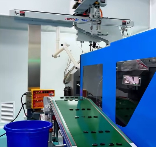
Send your part drawings, shortlisted resin grade, and target annual volume to sales@m-dtg.com or WhatsApp +86 133-1340-7440 to start a sample and quotation review. Download the full company presentation here: Xiamen DTG Tech Co., Ltd Presentation (PDF). More information is available at www.m-dtg.com. Address: Room 707, Yulong International Building 1, No.987, Anling Road, Xiamen 361006, Fujian, China.
Have Questions or Need More Details?
Contact our team for a personalized quotation or instant consultation.
Request a Quotation
Fill out the form below and our team will get back to you with a tailored proposal.
WhatsApp Direct Chat
Prefer to chat in real-time? Message us on WhatsApp for instant assistance & quick answers.
- Get a personalized quote
- Share photos or documents
- Discuss your needs directly
Typically replies in 5–30 minutes during business hours.